Aircraft Carburetors
You can contact us for parts of your aircraft and engine. You can also come straight to us for Repair and Overhaul of your carburetors Systems.Below there is a lay out on the operation of the Carburetor.
Below there is a lay out on the operation of the Carburetor.
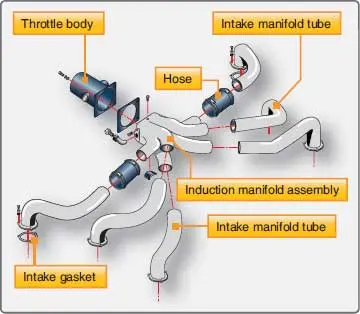
Two types of suction systems are often used in the engines of small aircraft:
1. Carburetor system, the fuel and air goes into the carburetor, where it mixes before this mixture enters the intake manifold.
2. The fuel injection system, so that the fuel and air are mixing just before they in each cylinder.
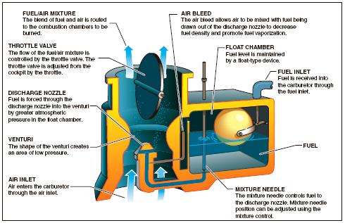
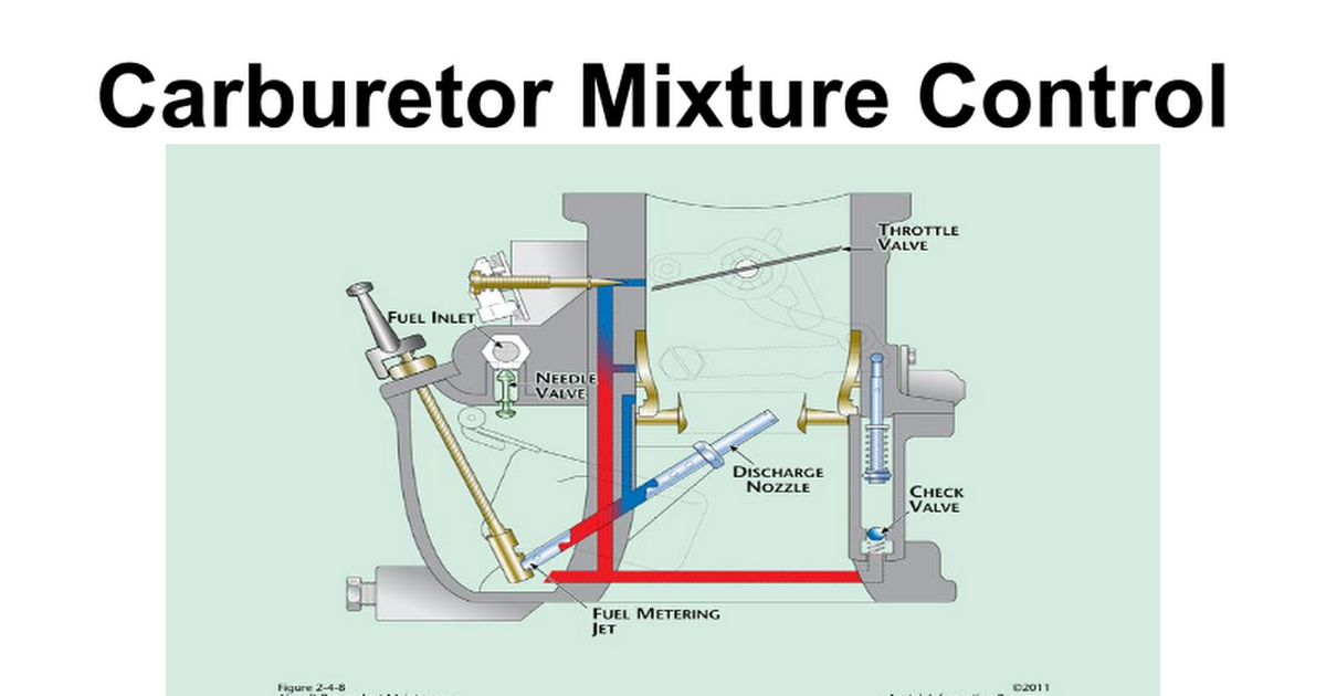
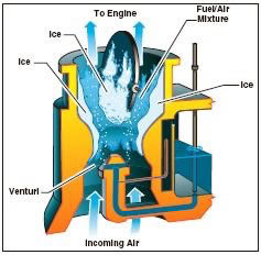
The fuel / air mixture is then drawn through the intake manifold into the combustion chambers, where it is ignited. The "float-type carburettor" gets its name from a float which rests on the fuel in the float chamber. A needle attached to the float opens and closes an opening at the bottom of the carburetor bowl. This ensures that the proper amount of fuel gets into the carburettor, depending on the position of the float, which is controlled by the fuel level in the float chamber. When the level of fuel is forced to increase the float needle valve closes the fuel opening and closes the fuel to the carburetor. The needle valve opens again when the engine requires extra fuel. The flow of the fuel / air mixture to the combustion chamber is controlled by the throttle valve, which is controlled by the throttle lever in the cockpit.
Two types of suction systems are often used in the engines of small aircraft:
1. carburetor system, the fuel and air goes into the carburetor, where it mixes before this mixture enters the intake manifold.
2. The fuel injection system, so that the fuel and air mixing just before they in each cylinder.
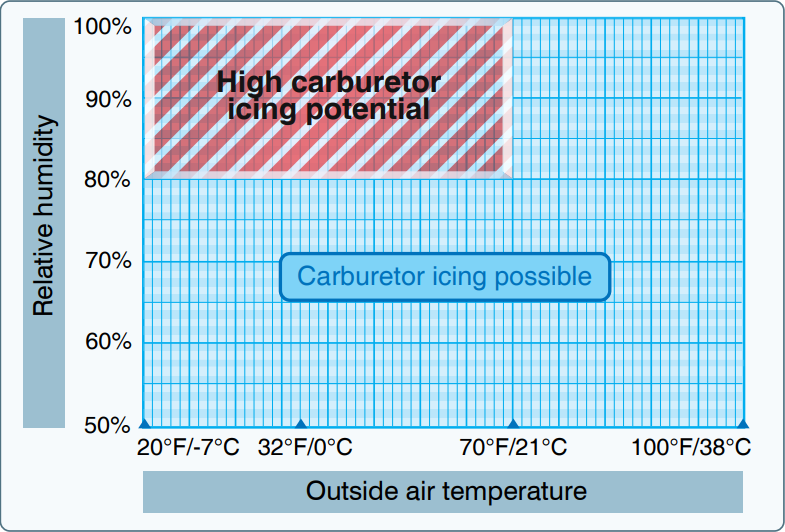
[The Figure shows that the formation of carburetor ice can reduce or block the fuel / air flow to the engine.]
The reduced air pressure, as well as the evaporation of the fuel, leads to the temperature reduction in the carburetor. Ice normally forms in the vicinity of the throttle valve and the venturi throat. This limits the flow of the fuel / air mixture and reduces power. If enough ice builds up, the engine can no longer work. Carburetor ice is most likely to occur at temperatures below 70 ° F (21 ° C) and when the relative humidity is above 80 percent. Because of the sudden cooling which takes place in the carburetor, ice can form even at temperatures of up to 100 ° F (38 ° C) and humidity as low as 50 percent prevented. This drop in temperature can be up to 60 to 70 ° F. Therefore, when there is an outdoor air temperature of 100 ° F and a temperature drop of 70 ° F. This causes an air temperature in the carburettor of 30 ° F.
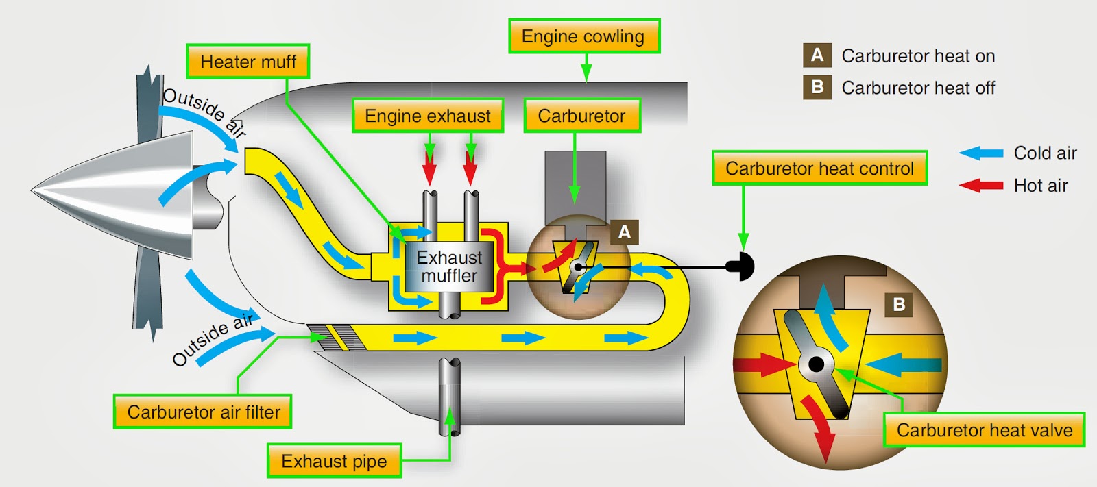
The first indication of the carburetor icing in an airplane with a fixed propeller is a decrease in the engine speed, which may be followed by engine roughness. In a plane with a constant speed propeller, carburetor icing is usually indicated by a decrease in manifold pressure, but no reduction rpm. Propeller pitch is automatically adjusted to compensate for the loss of power. Thus, a constant r.p.m. is maintained. Although carburettor ice can occur during any phase of flight, it is particularly dangerous when using a reduced flow during a descent. Under certain circumstances, the carburetor can build ice unnoticed until you try to give it to power. To combat the effects of carburetor ice, float-type engines with carburetors use a carburetor heating system.
The carburetor heat should be checked during the engine run up. In the use of carburetor heat, following the recommendations of the manufacturer.
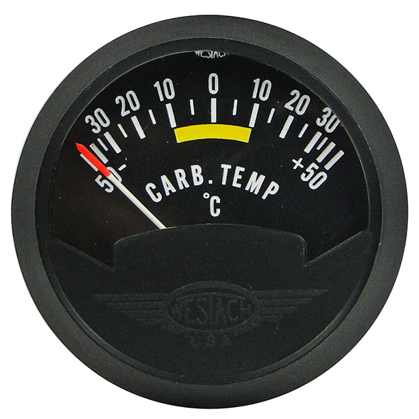
When conditions are conducive to carburetor icing during the flight, periodic checks should be done to detect his presence. If confirmed, the full carburetor heat is applied immediately, and it should be left in the ON position until you are sure all the ice has been removed. When ice is present, the application of a partial heat or leaving heat would worsen the situation in a sufficient time. In extreme cases of carburetor icing, even after the ice has been removed, full carburetor heat can be used to prevent further formation of ice. A carburetor temperature, if installed, is very useful in determining when to use carburetor heat.
When the throttle is closed during the flight, the engine quickly cools and the fuel evaporation is less complete than when the engine is warm. Also, in this state, the engine is more susceptible to carburetor icing. Therefore, if you suspect carburetor icing and anticipate closed throttle control, adjust the carburetor heat to the full ON position before closing the throttle, and leave it on during closed-throttle operation. The heat will assist in the vaporization of the fuel, and to help prevent the formation of the carburetor ice. Periodically, open the throttle smoothly for a few seconds to keep the engine warm, otherwise the carburetor heater can not generate enough heat to prevent icing.
The use of carburetor heat causes a power loss, sometimes up to 15 percent, because the heated air is less dense than the outside air that was in the engine. This enriches the mixture. When ice is present and carburetor heat is used in an airplane of fixed-pitch proppellor, there is a decrease in rpm, followed by a gradual increase in rpm when the ice melts. The RPM of the engine must also increase after the ice has been removed and carburator heat is OFF. If ice is not present and carburator heat is on, the r.p.m. decreases, then remains constant. When carburetor heat is used in a plane with a constant speed propeller and ice is present, a decrease in the inlet pressure will be noted, followed by a gradual increase. If carburetor icing is not present, the gradual increase in manifold pressure will not be clear until the carburetor heat is off. It is necessary that a pilot recognizes carburetor ice as it forms during the flight. These symptoms may be accompanied by vibrations of the engine. Once a power loss is noticed, action must be taken immediately to remove the ice already formed in the carburetor and prevent further icing. This is achieved by applying full carburetor heat, which will lead to a further reduction of the energy costs and possibly engine roughness as melted ice passes through the motor. These symptoms can last from 30 seconds to several minutes, depending on the severity of the icing. During this period, the pilot must resist the temptation to reduce carburator heat consumption. Carburetor heat must be returned in the full-cold position to normal flow.
Since the use of carburetor heat tends to reduce the output of the engine and also to increase the working temperature, carburetor heat should not be used at full power necessary (such as during take-off) or during normal engine operation, except for when carburator ice needs to be removed.
Some meters have a red radial carburetor air temperature gauge, which is the maximum permissible carburetor inlet air temperature that is recommended by the manufacturer of the motor; Also, a green arc can be included to indicate the normal operating range.
The team at Egmond Vintage Wings Maintenance are always on hand and happy to help. If you would like to enquire about any of our used machines for sale or maintenace, overhaul services, please complete the contact form on this page.
Email: info(@)evwmaintenance.nl
Tel: +31 (0)528 237132
Plesmanstraat 10
7903 BE Hoogeveen
The Netherlands
Airfield code: EHHO
KVK: 52756262